Reading A Wiring Diagram For Appliance
Repair
A wiring diagram is a drawing of the electrical circuit of whatever it is you
are working on. Often when working on appliances, it is necessary to read these
diagrams when there is an electrical problem with the appliance you are working
on. Knowing how to read a wiring diagram can save you from buying parts you
don’t need.
Every appliance comes with a diagram hidden on it somewhere such as under the
bottom, in the control panel behind the storage drawer or taped to the back. It
will be somewhere you will not find it unless you were looking for it.
On this page I will explain the basics on how to read a wiring diagram. The
type of diagram I will talk about is a ladder diagram because it is easy to read
and is the most common type of diagram. A ladder diagram looks like a ladder
just as the name suggests.
So if you have an electrical device that will
not work, look at the diagram and find the device. Everything between the two
main lines that the light is on can affect the light. Also you should know that
the main lines are marked L1, L2 and N. If a diagram has just L1 and N then the
circuit is 110V, if the diagram has L1 and L2 then it is a 240 circuit and if it
has L1, L2 and N it is a 110-220V circuit. Below is a picture of a few simple
ladder-wiring diagrams to help explain what I am talking about.
110V Light Circuit
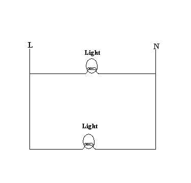
This first diagram is two very simple light circuits. From looking at this
diagram you should see that both lights run all the time because there isn’t a
switch to control them or a fuse. Also note that both lights run off of 110V
because they are connected between the L and the N.
110V Light Circuit With Switch And Fuse
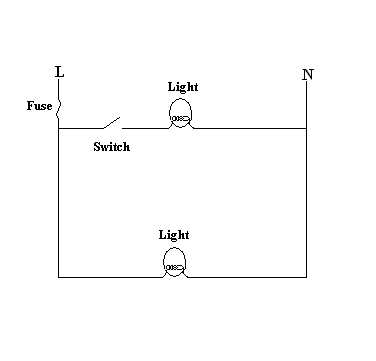
The next diagram is the same diagram only this time I stuck in a switch and a
fuse. You should notice that the fuse cuts both lights off and the switch only
turns off the top light. So the other light stays on all the time, provided the
fuse is not blown.
220V Light Circuit
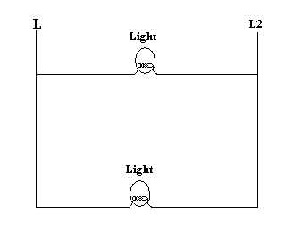
This diagram is the same as the first one only this time you should notice that
the lights run off of 240V because the circuit is connected between a L1 and L2
lines.
110-220V Circuit
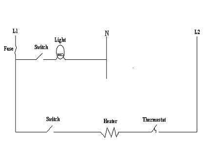
This diagram is a 110-220V circuit. There is a light that runs off of 110V and
is controlled by a switch. There is a heater that runs off of 220V and is
controlled by a switch and a thermostat. There is a fuse that turns both the
heater and the light off if it is blown.
Simple Dryer Circuit
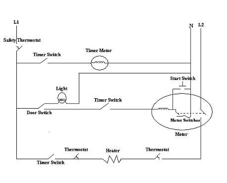
This is a simple dryer wiring diagram that shows examples of most of what you will see on many other wiring diagrams. I will break it down and explain each component of the dryer and how it is controlled.
The Motor
The motor is the most complicated part of this diagram. Notice that the motor
coils are connected to an internal motor switch, which is only closed if the
motor is running. This is why there is a start switch; the start switch
temporary bypasses the motor switch to allow the motor to run. Once the motor
starts, you no longer need the start switch because the motor switch takes over
so the start switch is only closed when you are pressing on it.
There is also a timer switch and a door switch that have got to be closed in
order for the motor to run. So when the timer is on, the door is closed and the
start switch is pressed, the motor will start. It runs off of 110V.
The heater
A timer switch, two thermostats and the motor switch control the heater. The motor switch will only close if the motor is running. One of the thermostats is for turning the heater on and off during normal operation. The other thermostat is for safety and will turn the heater off if it overheats. The timer switch is on when the timer is on and calling for heat. It runs off of 220V.
The timer
The timer motor runs until the timer switch turns it off and it stays off until someone comes and turns it on. This means that the timer turns off when it gets to a point. It runs off of 110V.
The light
The light is on when the door is open so that you can see inside the drum. It runs off of 110V.
The safety switch
The safety switch is a switch that cuts the entire dryer off if it overheats.
Note that this is not an actual dryer wiring diagram, it is just a sample I drew to help you understand wiring diagrams.
Return From Reading A Wiring Diagram For Appliance Repair